電磁感應
物理 · 共 35 題 · 點擊選項即時核對答案
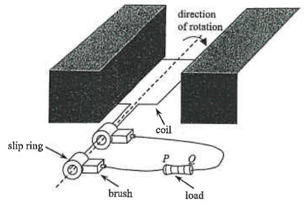
The diagram shows a generator connected to a load. Which of the following statements is/are correct ?
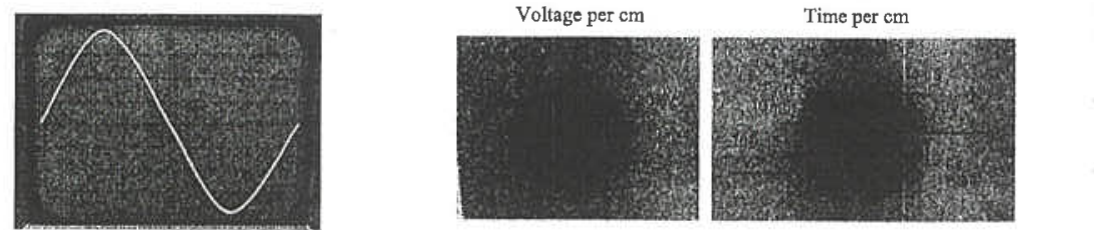
The photographs show the trace of a signal on a CRO and some settings of the CRO. The voltage gain is set at V per cm and the time-base is set at ms per cm. Find the frequency and peak voltage of the input signal.
| Frequency / Hz | Peak Voltage / V | |
|---|---|---|
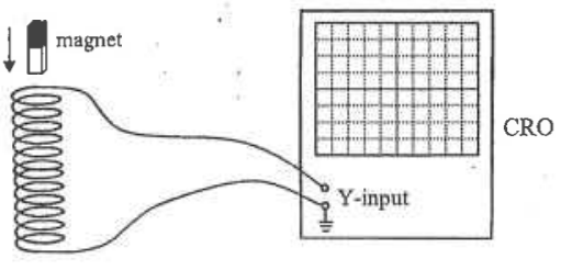
A long solenoid is placed in a vertical position and its two ends are connected to the -input of a CRO (with the time base switched on). A bar magnet is released above the solenoid so that it falls through the solenoid. Which of the following figures best represents the trace shown on the CRO ?

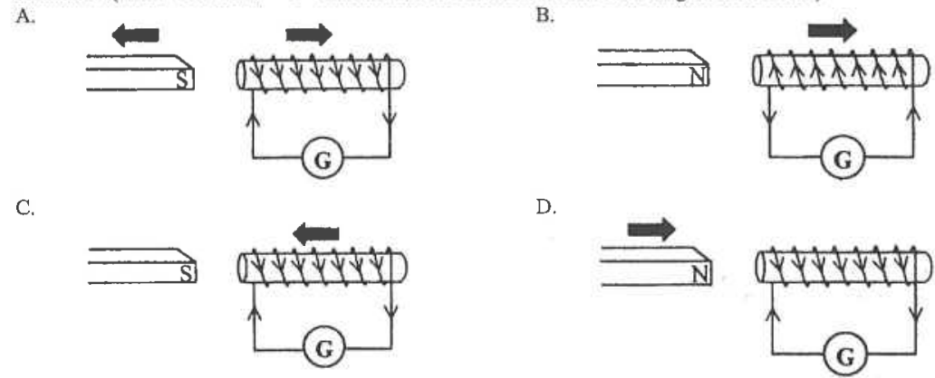
A bar magnet is placed near a solenoid. Which of the following correctly shows the direction of the induced current in the solenoid ? (Note : The arrow "" indicates the direction of motion of the magnet or solenoid.)
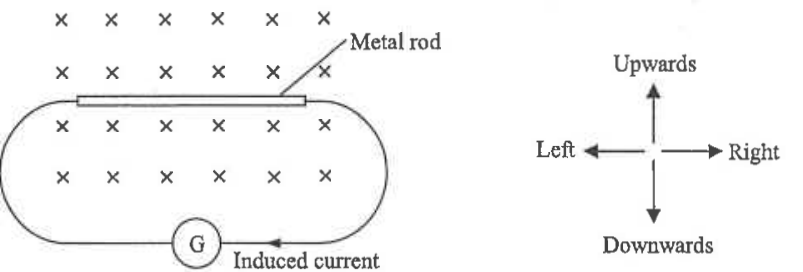
In the above diagram, a metal rod is placed inside a magnetic field pointing into the paper. In which direction should the rod be moved in order to produce an induced current as shown in the diagram ?
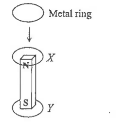
A metal ring is released and falls vertically around a magnet as shown in the above diagram. Which of the following diagrams correctly describes the directions of the induced current, if any, in the ring at positions and ?

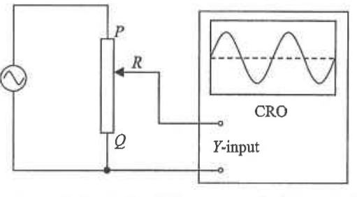
In the above circuit, the terminal and the sliding contact of the variable resistor are connected to the -input of a CRO. If is moved towards , how would the amplitude and period of the trace displayed on the CRO be affected ?
| Amplitude of the trace | Period of the trace | |
|---|---|---|
| increases | remains unchanged | |
| increases | increases | |
| decreases | remains unchanged | |
| decreases | decreases |
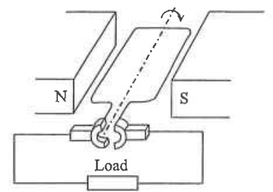
The diagram shows an electricity generator connected to a load. Which of the following can increase the voltage produced by the generator ?
Which of the following devices is not an application of electromagnetic induction ?
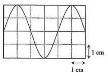
The diagram shows the display on a CRO with the time base at and -gain at . Find the peak voltage and frequency of the signal applied across the -plates.
| Peak voltage / V | Frequency / Hz | |
|---|---|---|